


Bluetooth® 5.1 – Why Do We Need Accurate Location and Direction Finding?
By Eve Danel
August 9, 2021LitePoint’s Eve Danel is the author of this blog. In this post, you’ll learn about the latest Bluetooth® specifications and new test requirements for Bluetooth® 5.1.
In 2010, Bluetooth® Low Energy (Bluetooth® LE) was introduced with the Bluetooth® 4.0 standard. Compared to previous generations of Bluetooth®, which were known as classic, Bluetooth® LE operates at lower power, increasing the battery life of host devices. In 2016, the Bluetooth® 5 standard was introduced, doubling the data rate and increasing the operation range. Bluetooth® 5.1 was released in 2019, adding direction-finding enhancements that enable location tracking applications.
Bluetooth® 5.1 Use Cases
With the direction-finding enhancements in Bluetooth® 5.1, the technology is able to provide GPS-like positioning capabilities but operating indoors. The use cases for this type of technology range from asset tracking to locating people in buildings, indoor direction finding, object tracking, among others. And this wide range of use cases can be applied in nearly every market vertical including industrial, medical, retail, hospitality, enterprise, home or transportation.
RSSI-Based Proximity Sensing
Bluetooth® is already a popular technology for proximity sensing using Bluetooth® beacons. In this method, the locator estimates distance using the received signal strength indicator (RSSI) value, which represents the strength of the signal that is measured on the locator’s receiver. RSSI is used to estimate the distance between a transmitter and a receiver. Knowing the transmitter’s power, it’s possible to estimate the location of an item by measuring signal attenuation.

Figure 1: RSSI based method
RSSI only provides a crude estimation of distance because this method is biased by the environment. Obstacles between the transmitter and receiver that provides attenuation – a crowd of people for example can add significant attenuation to the signal and therefore decrease the accuracy of the distance estimate. In addition, the RSSI method can only detect that the device is located somewhere in a circular zone around the receiver as shown in Figure 1 above as it doesn’t provide information about the position. By deploying multiple locators and using signal trilateration, it is possible to locate the device with more accuracy, but it also increases the complexity of the system.
Increasing Accuracy with Angle of Arrival and Angle of Departure
Bluetooth® 5.1 increases the accuracy of the RSSI method by providing angle of arrival (AoA) and angle of departure (AoD) information.
AoA is designed for use in applications like asset tracking, where a moving AoA transmitter (a mobile phone for example) is sending Bluetooth® LE direction-finding signals using a single antenna, and a fixed AoA receiver (for example installed on the ceiling) is equipped with an antenna array with a minimum of two antennas. The array is used to determine the direction of the transmitter by using the phase differences between the antenna. The angle of arrival determination is based on the signal’s wavelength, the distance between antenna and the phase of the received signal.
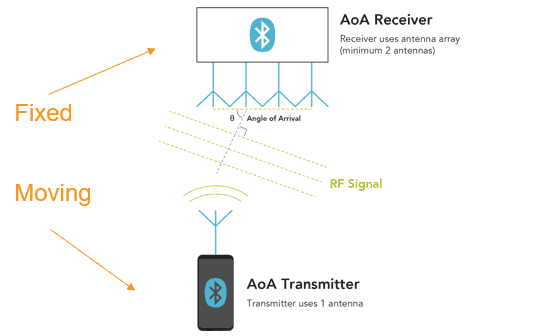
Figure 2: AoA method
AoD is designed for use in applications like wayfinding for indoor navigation. Where the AoD receiver (for example a phone) receives the direction-finding signal transmitted by the fixed AoD transmitter (for example installed on the ceiling) that is equipped with an antenna array with a minimum of two antennas. Just like AOA, the angle is determined by using the signal’s phase information.

Figure 3: AoD method
Bluetooth® 5.1 Constant Tone Extension (CTE)
To enable AoA and AoD, the signal’s phase must be measured. For direction finding, Bluetooth® 5.1 core specification adds a constant tone extension (CTE) field that is a sequence of bits with a variable duration from 16 microseconds to 160 microseconds. CTE is only supported for Bluetooth® LE operating at rates of 1 Mbps, which is mandatory, or, optionally, 2 Mbps. The CTE field contains a series of modulated 1 bits which must be transmitted at one frequency with a constant wavelength in order to measure the phase of the receive signal. Thus, the signal is not subject to whitening, a process that scrambles signals to ensure there will be no long strings of 1s or 0s.

Figure 4: CTE
How is Bluetooth® 5.1 Tested?
The key to a successful technology introduction for location services is how accurately the location can be measured, Bluetooth® 5.1 aims to provide a sub one-meter level of accuracy. Validation of the solution plays an important role in ensuring the system’s performance.
The Bluetooth® SIG has updated the Bluetooth® PHY test specifications to include validation of these new direction-finding capabilities. New test cases were added for transmitter and receiver tests for AoA and AoD methods, and the various combinations of Bluetooth® data rates that are supported in 1 Mbps and 2 Mbps, as well as the 1 microsecond and 2 microsecond switching and sampling times that are supported in the standard. Overall, there are 23 new test cases that were added to the PHY tests to cover AoA and AoD.
CTE is a new concept for Bluetooth® and the test cases are designed to ensure that it can be properly generated by the transmitter. On the receiver side, it’s important to ensure that the IQ measurements on the receiver CTE can be used to accurately derive the phase of the signal.

Figure 5: Complete AoA and AoD test setup
Figure 5 above shows a complete test setup for AoA and AoD transmitter and receiver testing. LitePoint’s IQxel-MW 7G supports the new direction-finding test cases. LitePoint also offers IQfact+ software packages that provide completely automated DUT and tester control for leading Bluetooth® 5.1 chipsets.
AoA Transmitter and Receiver Testing
In an AoA transmitter (typically a mobile device), the device has only a single antenna and the CTE field is transmitted continuously without switching at the end of the PDUs. On the received signal, the tester verifies the maximum peak and average power of the CTE signal as well as the carrier frequency offset and the carrier drift of these transmitted signals.
The AoA receiver is more complex because it has multiple antennas and a switch, so when receiving the CTE signal transmitted by the tester, the receiver will switch between the multiple antennas in the array according to a predetermined pattern. The time of the switching is either 1 microsecond or 2 microseconds as defined in the standard. The DUT also samples the received CTE during the allocated sampling slot’s timing of 1 microsecond or 2 microseconds as defined in the standard. The IQ samples taken by the DUT are transmitted to the tester for analysis to ensure that the phase measurements are within specs.
AoD Receiver and Transmitter Testing
An AoD receiver (mobile device with single antenna) needs to sample the received CTE signal at the correct sampling slots. To verify this, the IQ samples that are taken by the DUT are transmitted to the tester for processing and analysis. Just like with the AoA receiver test, this test verifies that the phase values derived from the sampling are within specs.
AoD transmitter devices have an antenna array with a minimum of 2 antennas, therefore the transmitter test verifies that the antenna switching occurs during the proper allotted slots of the CTE and the proper switching pattern within antenna array.
Please visit the IQxel-MW 7G and IQfact+ pages for more information on LitePoint’s test solutions for Bluetooth® 5.1.
For more information download our application note on Testing Bluetooth® 5.1 or download the replay of our webinar on this topic.
Categories
Subscribe to the LitePoint Blog
Related Posts
