


Wi-Fi 6 OFDMA – How Does it Work and How Do You Test?
By Eve Danel
June 29, 2021LitePoint’s Eve Danel is the author of this two-part blog series. Throughout these posts, you’ll learn about the key RF-PHY changes made in Wi-Fi 6/802.11ax compared to Wi-Fi 5 and older generations: the addition of a new frequency band, higher modulation rates, smaller subcarrier spacing, longer guard intervals and the introduction of the OFDMA modulation technique providing capacity improvements and latency reduction.
In my previous blog post, I explored some of the key RF-PHY changes in Wi-Fi 6, including a fundamental change to the way that Wi-Fi 6 operates, which is using orthogonal frequency division multiple access (OFDMA). Let’s take a closer look at Wi-Fi 6 OFDMA.
Resource Units (RUs)
With OFDMA, the channel bandwidth is divided into resource units (RUs) of various sizes. The size of an RU can vary from the smallest 26 subcarriers (or 2 MHz) up to 996 tones (or 77.8 MHz). The size and the location of the RUs is defined for 20 MHz, 40 MHz, 80 MHz channels, and 80+80 or 160 MHz channels.

Figure 1: RU location in 80 MHz channel
RUs are comprised of:
- Data subcarriers used to carry data information and form the majority of the subcarrier’s assignment
- Pilot subcarriers used for phase tracking for channel estimation
- DC subcarriers at the center frequency of the channel
- Guard band/Null subcarriers used at the band edges to protect from interference from neighboring RUs
Different numbers and sizes of RUs can be allocated for transmissions to different users, based on how much data each station needs. The access point (AP) is responsible for RU assignment and coordination. For example, applications that require a lot of data, like streaming video, can be assigned a large RU, while applications that require very little data can be assigned a small RU. Each RU can use a different modulation scheme, coding rate and level, and RU assignments can vary on a frame by frame basis.
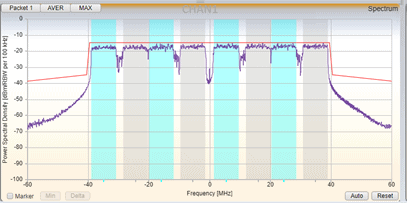
Figure 2: OFDMA transmission showing 80 MHz channel divided into 8 RUs
Wi-Fi 6 OFDMA Downlink Transmissions
For a downlink transmission, an HE MU PPDU carrying a mixture of 26-, 52-, 106-, 242-, 484-, and 996-tone RUs is transmitted from the AP to the stations. The HE MU PPDU preamble is transmitted over the whole channel and contains a new field called the SIG-B that provides information to the stations about their RU size and frequency allocation, the modulation MCS and the number of spatial streams allocated by the AP.

Figure 3: HE MU PPDU
The HE-SIG-B field is only included in HE MU PPDU (downlink) and it includes the information for OFDMA and MU-MIMO resource allocation. The HE-SIG-B field includes a common field followed by user specific fields.
The common field of an HE-SIG-B content channel contains information regarding the RU assignment, the RUs allocated for MU-MIMO and the number of users in MU-MIMO allocations. The SIG-B user specific fields contain information for all users in the PPDU on how to decode their payload.
Wi-Fi 6 OFDMA creates a large number of permutations of possible RU sizes, frequency allocations and power levels that need to be validated to ensure the transmitter and receiver performance meets the standard criteria. All of these permutations can have different error vector magnitude (EVM) and spectral performance.
Wi-Fi 6 OFDMA Uplink Transmissions
Wi-Fi 6 OFDMA uplink transmissions are even more complex than downlink operation, because in the uplink, the traffic must be transmitted simultaneously from multiple stations to the AP. In the uplink transmission, the AP acts as an operations and transmission coordinator.
First, the AP sends a trigger frame to all the stations that will be involved in the upcoming transmission, and then these stations transmit simultaneously on their respective RUs in response to the trigger frames. Based on the trigger frame, the client station will need to tune its timing, frequency and power levels to participate in this transmission.
Timing synchronization
Client stations participating in an OFDMA transmission must transmit within 400 ns of each other. In order to synchronize the clients, the AP transmits a trigger frame. This frame contains information about the OFDMA sub-carrier’s RU assigned to each station. In response, the participating clients need to start transmission of the uplink signal after a specified time interval short inter-frame space (SIFS) of 16 µs +/- 400 ns after the end of the trigger frame as mandated by the 802.11ax standard.

Figure 4: Timing synchronization of uplink OFDMA
Frequency synchronization
To prevent inter-carrier interference (ICI) between the clients transmitting simultaneously, all stations participating in the transmission need to pre-compensate for carrier frequency offset (CFO). The client stations adjust their carrier frequency based on the trigger frame received from the AP. The 802.11ax standard requires the residual CFO error after compensation to be less than 350 Hz.

Figure 5: Wi-Fi OFDMA frequency synchronization
Power control
When traffic is transmitted between the AP and client stations that are located at various distances, power control is needed to ensure that stations closer to the AP do not drown out users farther from the AP that are transmitting simultaneously. The 802.11ax standard requires the stations to adjust their power based on the estimated path loss to the AP. Devices closer to the AP transmit less power while devices farther away transmit more power to achieve the same received power at AP receiver considering the path loss. There are two classes of devices defined in the standard based on how accurately they can control their power. Class A devices control their transmit power within ±3 dB and class B devices control their power within ±9 dB.
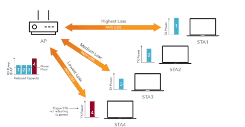
Figure 6: Wi-Fi OFDMA power control
The accuracy of the synchronization between the AP and the client is critical because a single bad actor (station) that doesn’t perform as expected will degrade performance for all other users that are sharing the same transmission.
Unused Tone EVM
Another concept introduced in Wi-Fi 6 OFDMA is the unused tone EVM metric. As discussed above, when the stations transmit in the uplink direction on their assigned RU, it is important that emissions do not spill over into other RUs, otherwise that will reduce the system capacity for other users.

Figure 7: Unused tone EVM
To evaluate the station’s performance, the 802.11ax standard introduced this new metric, which is a measure of the in-channel emissions generated by the stations. IEEE specifies RU leakage as a staircase mask requirement, which is called unused tone EVM. The unused tone EVM measures the EVM floor of 26 tone RU over the whole channel bandwidth excluding the position(s) for the active RU.
Wi-Fi 6 OFDMA Uplink Trigger-Based Testing
The validation of uplink multi-user transmission in Wi-Fi 6 OFDMA is one of the most challenging areas of 802.11ax testing. For the tester, it requires the involvement of both the signal generation and signal analysis function, which need to be coordinated to run a test sequence to provide nanosecond-level accuracy measurements to ensure the required 400 nanosecond accuracy of the uplink transmission.
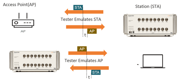
Figure 8: Wi-Fi 6 trigger-based testing
When testing an AP design, the tester emulates a station, and it decodes the received trigger frame information in order to generate a trigger-based physical layer protocol data unit (PPDU) with the correct RU allocation. The tester also needs to adjust its power to the AP requirements in real time because it needs to respond to the AP with a nanosecond level of accuracy.
When testing a client station, the tester emulates an AP, generates a trigger frame and will measure the response with the signal analysis function. The tester measures the trigger-based PPDU generated by the station itself. The tester needs to measure the timing, frequency and power accuracy of this transmission from the client to ensure it meets the 802.11ax standard requirements and the RU leakage requirements.
Conclusion
Beyond testing the traditional transmit and receiver metrics that are necessary for any Wi-Fi generation, the chart below shows an overview of the new test areas that are specific to 802.11ax. These test sequences for Wi-Fi 6 OFDMA require a higher level of test complexity compared to previous Wi-Fi generations.

Figure 9: Wi-Fi 6 key test areas
If the number of test cases and complexity of Wi-Fi 6 OFDMA seems overwhelming, I encourage you to explore LitePoint’s IQfact+ automation solution. The software is tailored to control both the tester and the device under test (DUT) and it provides calibration and verification automation. LitePoint already offers IQfact+ packages for Wi-Fi 6 and Wi-Fi 6E chips for AP and client devices.
For more on Wi-Fi 6 OFDMA, please download the full replay of my webinar on this topic.
Categories
Subscribe to the LitePoint Blog
Related Posts
Wi-Fi 6 vs. Wi-Fi 5 Key Changes to the RF Physical Layer
May 25, 2021
Wi-Fi 6E Standard and Channels – 802.11ax Operation in the 6 GHz Band
November 11, 2020
An Introduction to Wi-Fi 6E Spectrum in the 6 GHz band – Wi-Fi’s First Unlicensed Spectrum Boost in 20 Years
October 26, 2020
